
Page 120 - CNC Robotics
P. 120
Chapter 4 / Driver Assembly
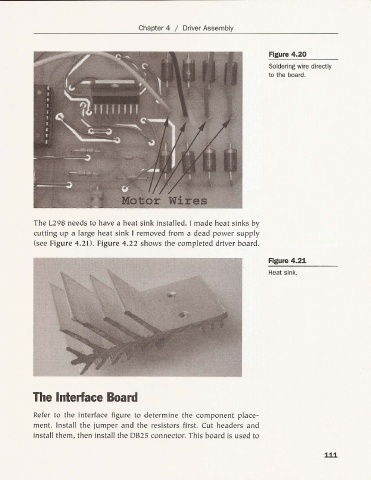
Figure 4.20
Solderingwire directly
to the board.
The L298 needs to have a heat sink in stalled. I made heat sinks by
cutting up a large heat sink I removed from a dead power supply
(see Figure 4.21). Figure 4.22 shows the completed driver board.
Figure 4.21
Heat sink.
The Interface Board
Refer to the interface figure to determine the component pla ce-
ment. Install the jumper and the resistors first. Cut headers and
in stall them , then install the OB25 connector. This board is used to
111