
Page 118 - CNC Robotics
P. 118
Chapter 4 / Driver Assembly
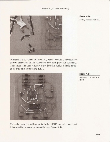
Figure 4.16
Cutting header material.
To install the Ie socket for the L297, bend a couple of the leads-
one on either end of the socket-to hold it in place for solderi ng.
Then insta ll the L298 direct ly to the board. I cou ldn't fin d a sock -
et for th is chip (see Figure 4.17).
Figure 4.17
Installing Ie holder and
L298 .
The only capacitor with polarity is the 470UF, so make sure that
this capacitor is installed correctly (see Fig ure 4. 18).
109