
Page 113 - CNC Robotics
P. 113
CNC Robotics
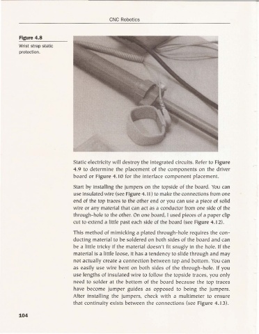
Figure 4 .8
Wrist strap stat ic
protection.
Static electricity will destroy the integrated circuits. Refer to Figure
4.9 to determine the placement of the components on the driver
boa rd or Figure 4. 10 for the interface component placement.
Start by installing the jumpers on the topside of the board. You ca n
use insulated wire (see Figure 4.11) to make the con nections from one
end of the top traces to the other end or you can use a piece of solid
wire or any material tha t ca n act as a conductor from one side of the
through-hole to the other. On one board, I used pieces of a paper clip
cut to extend a little past eac h side of the boa rd (see Figure 4.12).
This method of mimicking a plated thro ugh -hole requi res the con-
ducting material to be soldered on both sides of the board and ca n
be a little tricky if the material doesn't fit snug ly in the hole. If the
material is a little loose, it has a tendency to slide through and may
not actually create a connection between top a nd bottom. You can
as easily use wire be nt on bot h side s of the through-hole. If you
use lengths of insulated wire to follow the topside traces, you on ly
need to so lder at the bottom of the boa rd because the top traces
have become jumper guides as opposed to bei ng the jumpers.
After installin g the jumpers, check with a mu ltimeter to ensure
that continuity exis ts between the connec tions (see Figure 4.13).
104