
Page 114 - CNC Robotics
P. 114
Chapter 4 / Driver Assembly
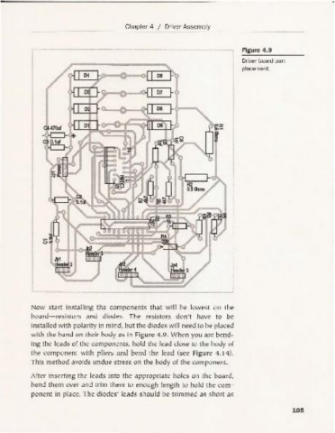
Figure 4.9
Driver board part
placement.
~Jca.......~...c:<,~
o
~ b--.......
Jp1
Header3
~
Now start installing the components that will be lowest on the
board-resistors and diodes. The resistors don't have to be
installed with polarity in mind, but the diodes will need to be placed
with the ba nd on their body as in Fig ure 4.9. When you are bend-
ing the leads of the compo nents, hold the lead close to the body of
the component with pliers and bend the lead (see Figu re 4.14).
This method avoids undue stress on the body of the component.
After inserting the leads into the appropriate holes on the board,
bend them over an d trim them to enough length to hold the com-
ponent in place. The diodes' leads sh ould be trimmed as short as
105