
Page 110 - CNC Robotics
P. 110
Chapter 4 I Driver Assembly
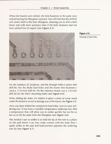
When the boards were etched, the hole locations in the pads were
etched leaving the fiberglass exposed. You will find that the dri ll bit
will center itself to the bare fiberglass, allowing you to drill a little
faster and with more accuracy than if the hole location s had not
been etched free of copper (see Figure 4. 3).
Figure 4.3
Closeup of pad hole.
For the resistors, Ie locations, and the through-holes I used a #60
drill bit. For the diode lead holes and the motor wire locations I
used a II 16-inch drill bit. On the interface board, use a IIS- inch
drill bit for the OB25 mou nting holes (see Figure 4.4).
When drilling the holes, it's helpful to place a piece of scrap wood
under the board so as not to damage any of the traces. See Figure 4.5.
Once you have drilled the component lead hole s, turn on your sol-
dering iron. If you have a varia ble-temperature soldering iron , find
a temperature that will allow you to solder quickly but not be so
hot as to lift the pads from the fiberglass (see Figure 4.6).
The method I use to solder is to hold the tip of the iron to a place
on the pad where I can also ma ke contact with the lead; then I
apply solder to the pad and lead junction opposite the soldering
iron tip (see Figure 4.7).
101