
Page 178 - CNC Robotics
P. 178
Chapter 7 / The Gantry and X-axis
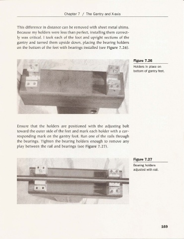
This difference in dis tance can be removed with sheet metal shims.
Because my holders were less than perfect, installing them correct-
ly was critical. I took each of the foot a nd upright sections of the
gantry and turned them upside down, placing the bearing holders
on the bottom of the feet with bearings installed (see Figure 7.26).
Figure 7.26
Holders in place on
bottom of gantry feet.
Ensure that the holders are positioned with the adjusting bolt
toward the outer side of the feet and mark each holder with a cor-
responding mark on the gantry foot. Run one of the rails through
th e bearings. Tighten the bea ring holders enough to remove any
play between the rail and bearings (see Figure 7.27).
Figure 7.27
Bearing holders
adjusted with rail.
169