
Page 18 - CNC Robotics
P. 18
CNC Robotics
Because I only have a space 12 X 22 feet a nd tools and materi-
als currently occupy most of that space, my machine wo uld only
be ab out 7 feet long and 4 feet wide. The next step in this projeci
was to ge nerate concept drawings, since I was going to use some
of the components from the NuArc horizontal camera. The
dimensions of the frame ended up being longer than the support
rails in order to accommodate the bearing holders and the motor
mount with a little room 10 spare. The width of the frame is a few
inches shorte r than the balance of a 6-foot acme lead screw, after
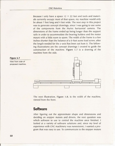
the length needed for the z-axis has been cut from it. The follow-
ing illustrations are the concept drawings 1 created to guide the
co nstruction of the machine. Figure 1.7 is a drawing of the
machine from the side.
Figure 1.7
View from side of
proposed machine.
The next illustration, Figure 1.8, is the width of the machine,
viewed from the front.
Software
After figuring out the approximate shape and dimensions and
deciding on stepper motors and drivers, the next question was
which software to use to control the machine once finished. 1
looked at a variety of software solutions and, since my level of
experience with CNC machinery was nonexistent, I wanted a pro-
gram that was easy to use. To communicate to the stepper moto rs
10
r- - - - - - - - - - - - - - - - - - - - - - - - - - - - -