
Page 24 - CNC Robotics
P. 24
CNC Robotics
the computer, they translate the information into higher voltage
and amperage signa ls to send to the stepper motors. The power
sent to the stepper motor coils is distributed to the coils in a
sequence that will move the shaft in the desired direction as many
steps as are needed to traverse the distance required on that axis .
For th is project we need three driver boards. one for each axis of
travel. The boa rds are designed using a set of in tegrated circuits
manu factured by STMicroelect rion ics- the L297 and L298. The
nice thing about using th ese two chi ps is that th e boa rd design is
quite simple. only requiring a min ima l number of components. A
second benefit is that when com bined, these two chips create a
very powerful driver board capable of handling up to 36 volts and
2 amperes per channel. A lot of bipolar and uniploar stepper
motors currently manufactured or available as surplus. which are
strong enough to be used for this machine. are well within the tol-
erances of these chips. The steppers that I decided to use are
Sanyo Denki step-syn and are rated at 4.5 volts and 1.4 amps per
channel wi th a resolution of 2 degrees per step. The power rat ings
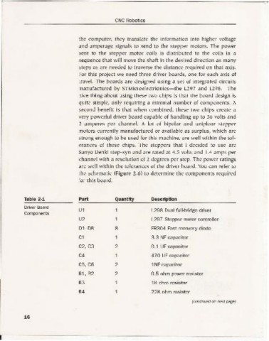
are well wi th in the tolera nces of the driver boa rd. You can refer to
the schematic (Figure 2.6) to determ ine the components requ ired
for this board.
Table 2-1 Part Quantity Description
Driver Board
Ul 1 L298 Dual full-bridge driver
Components
U2 1 L297 Stepper motor controller
Dl-D8 8 FR304 Fast recovery diode
Cl 1 3.3 NF capacitor
C2,C3 2 0.1 UFcapacitor
C4 1 470 UF capacitor
C5, C6 2 lNF capacitor
Rl, R2 2 0.5 ohm power resistor
R3 1 lK ohm resistor
R4 1 22K ohm resistor
(continued onnext page)
16
I ~~~~~~~~~~~~~~~~~~~~~~~~~-