
Page 27 - CNC Robotics
P. 27
CNC Robotics
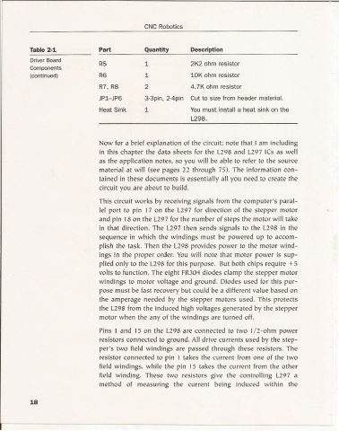
Table 2-1 Part Quantity Description
Driver Board
R5 1 2K2 ohm resistor
Components
(continued) R6 1 10K ohm resistor
R7, R8 2 4,7K ohm resistor
JP1-JP6 3-3pin, 2-4pin Cut to size from header material.
Heat Sink 1 You must install a heat sink on the
1.298.
Now for a brief explanation of the circuit ; note that I am incl uding
in this chapter the data sheets for the L298 and L297 ICs as well
as the applicat ion notes, so yo u will be able to refer to the source
material at will (see pages 22 through 75). The information con -
tained in these documents is essentially all you need to create the
circui t you are about to build.
This circuit works by receiv ing signa ls from the computer's paral-
lel po rt to pin 17 on the L297 for direction of the stepper motor
and pin 18 on the 1.297 for the number of steps the motor will take
in that directi on . The L297 th en sends signals to the 1.298 in the
sequence in w hich the windings must be powered up to accom-
pli sh the task. Then the 1.298 provides power to the motor wind-
ings in th e proper order. You will note that motor power is sup-
plied only to the L298 for this pu rpose. But both chips require +5
volts to fu nction. The eight FR304 diodes cla mp the stepper motor
windings to motor voltage and ground. Diodes used for this pur-
pose must be fast recovery but could be a different value based on
the amperage needed by the stepper motors used. Th is protects
the L298 fro m the induced high voltages generated by the stepper
moto r w hen the any of the windings are turned off.
Pins I and 15 on the L298 are connected to two 1/ 2-ohm power
resistors connected to ground. All drive currents used by the step-
per's two field w indings are passed through th ese resistors. The
resistor connected to pin I takes the current from one of th e two
field w indings, w hile the pin 15 takes the curre nt from the othe r
field winding. These two resistors give the controlling 1.297 a
method of measuring the current being induced within the
18