
Page 30 - CNC Robotics
P. 30
Chapter 2 / Electronics
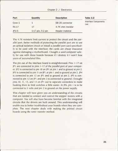
Part Quantity Description Table 2.2
Interface Components
Conn 1 1 DB 25 connector
List
Rl-17 17 4.7K ohm resistor
JPl-5 1-17 pin, 5-2 pin Header material
Th e 4.7 K resistors limit curren t to protect the circuit and the par-
all el port. Better methods of protecting the parallel port are to use
an optical isolation circuit or install a parallel port card specifical-
ly to be used w ith the interface; the cards are cheap insurance
against damaging a motherboard. I bought a used computer sole-
ly for use with these boards becau se if I destroy it I won't lose
years of accumulated file s.
The pin out of the interface board is straightforward. Pins 1-17 on
jP1 are conn ected to pins 1-1 7 of the parallel port of your comput-
er. jP2 is conn ected to pin 10on jP I at pin 1 and to ground at pin 2.
jP3 is conn ected to pin lion jPl at pin 1 and to ground at pin 2. jP4
is conn ected to pin 12 on [P1 and to ground at pin 2. jP5 is con-
nected to pin 13 on IPI and pin 2 is connected to ground. I brought
pin s 10, II , 12, and 13 on JP lout to separate conn ectors to make
hooking them to limit switches a little easier. At JP6, pin I is to be
connected to 5 volts and pin 2 to ground on the power supply.
This chapter w ill have given you an und erstanding of the circuits
that are needed to connect and control the stepper motors with a
computer. You w ill also have become familiar with th e integrated
circuits that the drivers are built around. This understanding will
enabl e you to bett er troubleshoot your boards when they are com -
plete. The next chapter deals w ith making the printed circuit
boards using the toner transfer method.
I
21
l- - - - - - -