
Page 33 - CNC Robotics
P. 33
CNC Roboti cs
L297·l297D
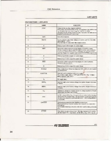
PIN FUNCTIONS - l2971L297D
N' NAME FUNCTION
1 SYNC OUtput of the on-ch ip chopper oscillator.
The SYNC connections The SYNC co-oecnco s 01all l297s to be
synchrooized are coonecled toge the r and the oscillator
components are omitted on all but one. If an external clock so urce
is used it is injected at this terminal.
2 OND Ground connec tion.
3 HOME Ope n co llector output that indicates wh en the l297 is in its initial
slate (ABeD = 0101).
The transistor is open when this signal is active.
4 A Motor phase A drive signal for pow er stage .
5 INHl Active low inhibit control for dri ver stage of A and B phases.
When a bipola r bridge is used this signal ca n be used 10 ensure
fas! decay of load current when a winding is de-e nergi zed . Also
used by chopper 10 regulate load current if CONT ROL input is low.
6 B Motor pha se 8 drive signal for power stag e.
7 e Motor pha se C drive signa l for pow er stage .
S INH2 Activ e low inhibit con trol for drive stages of C and 0 phases.
same functi ons as INH 1.
I. D Motor phase 0 drive signal for power stage .
9
Chip ena ble input. When low (inactiv e) INH1. INH2 , A. B, C and D
ENABLE
are brought low.
11 CONTROL Control input that del ines action of chopper.
When low chopper acts on INHl and INH2; when high chopper
acts on pha se lin es ABCD.
12 V. 5V supply input.
13 SENS 2 Input lor load current sense voltage from power stages 01phases
C and D.
14 SENS , Input lor load curre nt sense voltage from power stages 01phases
A and B.
15 V. , Reference volta ge lor chopper circuit. A volage applied to this pin
determines the peak load current.
,. ose An RC network (A to Vee. C to ground) comected to this terminal
determines the chopper rate.This term inal is connecled 10 ground
on all but one device in synchroniz ed multi - l297 confi gurations. I
== 1I0.69RC
17 CWICCW Clockwiseicountef'Clod(wise direction control inpul.
Physical direction 01motor rotation also depends on connection
of windings.
Synchronized intemally therefore direction can be changed at any
tim e.
18 CLOC K Step clock. An active low pulse on this input advances Ihe motor
one inc reme nt. The step occurs on the rising edge 01this signal.
3/11
--------- liii SGS.~ ...::c.:.
24
I