
Page 34 - CNC Robotics
P. 34
Chapter 2 I Electron ics
1297·12970
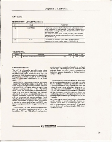
PIN FUNCTIONS . l2971L297D(conlinued)
,. NAME FUNCTION
N'
HAl F/FUU Halflfull step select input. When high selects half step operation,
when low selects lun step ope ration . On e-phase-on full step mode
is obtained by sel ecting FULL wh8f1 the l297'stranslator is at an
eveo-numoered slate.
Two-phase-on lull step mode is set by selecting FULL whe n the
translator is at an odd numbered position. (The hom e position is
designate state 1).
20 RES ET Reset input An active low pulse on this input restores the
translator to the home posi tion (state 1, ABeD= 0101).
THERMAL DATA
Symb04 Parameter DIP20 SOlO Unit
Thermal resistance junction-ambient max 80 100 oem
are cho pped the non-activephase line of each pair
CIRCUIT OPERATION
(AB or CD) is activated(ratherthan interrupting the
The LZ97 is intended for use with a dual bridge line then active). In L297 + L298 conf igurations this
driver, quad darlington array or discrete power technique reduces dissipation in the load current
devices in step motor driving applications. It re- sense resistors.
ceives step clock,direction and mode signals from
the systems controlle r (usually a microcomputer
chip) and generates control signals for the power
stage. A common on-chip osc illator drives the dual chop-
The principal functionsare a translator,which gen- per.lt suppliespulses at the cho ppe r rate which set
erates the motor phase seque nces, and a dual the two flip-flops FF1 and FF2. When the cu rrent in
PWM choppercircuit which regulatesthe current in a winding reaches the prog rammed peak value the
the motor windings.The translator generates three voltage across the sense resistor (connected to
different sequences , selected by the HALF/FU LL one of the sense inputs SENSl or SEN&?) equals
input. These are normal (two phases energised ), Vral and the correspo nding comparator resets its
wave drive (one phase energised) and half-step flip flop, interrupting the drive current until the next
(alternately one phase energised/two phases en- oscillator pulse arrives. The peak current for both
ergised) .Two inhibit signals are also generated by windings is programmedbya voltaged ivideron the
the l297 in half step and wavedrive modes.These V,al input.
signals, which connect directlyto the L298'senable Ground noise problems in multiple confi gurations
inputs, are intended to speed current decay when can be avoided by synchronising the chopper os-
a winding is de-energised.When the L297 is used cillators. This is done by connecting all the SYNC
to drive a unipolar motor the chopper acts on these pins together. mounting the oscillator RC network
lines. on one device only and grounding the OSC pin on
An input called CONTROL determ ines whethe rthe all other devices .
chopper will act on the phase lines ABCD or the
inhibit lines INH1 and INH2. When the phase lines
4111
25