
Page 360 - Caldera Volcanism Analysis, Modelling and Response
P. 360
Magma-Chamber Geometry, Fluid Transport, Local Stresses and Rock Behaviour 335
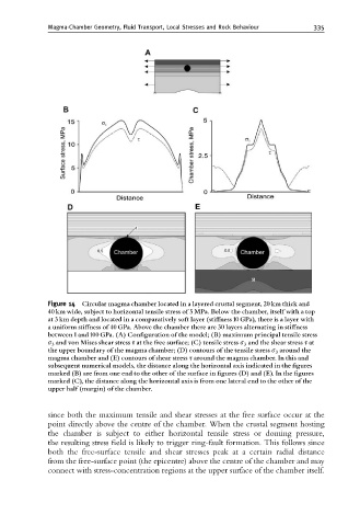
Figure 14 Circular magma chamber located in a layered crustal segment, 20 km thick and
40 km wide, subject to horizontal tensile stress of 5 MPa. Below the chamber, itself with a top
at 3 km depth and located in a comparatively soft layer (sti¡ness 10 GPa), there is a layer with
a uniform sti¡ness of 40 GPa. Above the chamber there are 30 layers alternating in sti¡ness
between 1and 100 GPa. (A) Con¢guration of the model; (B) maximum principal tensile stress
s 3 and von Mises shear stress s at the free surface; (C) tensile stress s 3 and the shear stress s at
the upper boundary of the magma chamber; (D) contours of the tensile stress s 3 around the
magma chamber and (E) contours of shear stress s around the magma chamber. In this and
subsequent numerical models, the distance along the horizontal axis indicated in the ¢gures
marked (B) are from one end to the other of the surface in ¢gures (D) and (E). In the ¢gures
marked (C), the distance along the horizontal axis is from one lateral end to the other of the
upper half (margin) of the chamber.
since both the maximum tensile and shear stresses at the free surface occur at the
point directly above the centre of the chamber. When the crustal segment hosting
the chamber is subject to either horizontal tensile stress or doming pressure,
the resulting stress field is likely to trigger ring-fault formation. This follows since
both the free-surface tensile and shear stresses peak at a certain radial distance
from the free-surface point (the epicentre) above the centre of the chamber and may
connect with stress-concentration regions at the upper surface of the chamber itself.