
Page 364 - Caldera Volcanism Analysis, Modelling and Response
P. 364
Magma-Chamber Geometry, Fluid Transport, Local Stresses and Rock Behaviour 339
somewhat higher than those at the free surface, a ring dyke would also be expected
to form.
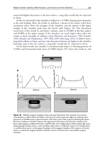
In the second model, that chamber is subject to a 10 MPa doming stress (pressure)
as the only loading. Here, the tensile s 3 and shear t stresses at the surface reach their
maximum values above the margins of the chamber, and the stresses at the upper
margin of the chamber peak near the lateral ends (Figure 18). The theoretical
maximums of the tensile s 3 and shear t stresses, close to 20 MPa at the free surface
and 40 MPa at the upper margin of the chamber, are much higher than either the
tensile or shear strengths of ordinary rocks (Haimson and Rummel, 1982; Schultz,
1995; Amadei and Stephansson, 1997; Bell, 2000; Myrvang, 2001). It follows that a
ring fault is likely to form, and since the theoretical stresses are higher at the chamber
boundary than at the free surface, a ring dyke would also be expected to form.
In the third model, the chamber is simultaneously subject to doming pressure of
10 MPa and horizontal tensile stress of 5 MPa (Figure 19). Here, the tensile s 3 and
Figure 18 Sill-like magma chamber, 8 km wide and 2 km thick.The chamber is located at
3 km depth in a 20 km thick and 40 km wide layered crustal segment subject to doming stress
(pressure) of 10 MPa at the segment bottom.The lower part of the segment (hosting the cham-
ber) has a sti¡ness of 40 GPa, whereas the uppermost 3 km above the chamber consists of 30
layers alternating in sti¡ness between 1and 100 GPa. (A) Con¢guration of the model; (B) maxi-
mum principal tensile stress s 3 and von Mises shear stress s at the free surface; (C) tensile stress
s 3 and the shear stress s at the upper boundary of the magma chamber; (D) contours of tensile
stress s 3 around the magma chamber and (E) contours of shear stress s around the magma
chamber.