
Page 361 - Caldera Volcanism Analysis, Modelling and Response
P. 361
336 Agust Gudmundsson
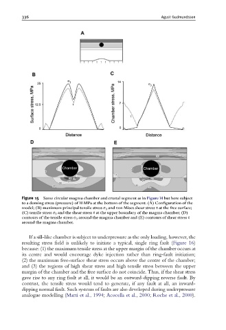
Figure 15 Same circular magma chamber and crustal segment as in Figure14 but here subject
to a doming stress (pressure) of 10 MPa at the bottom of the segment. (A) Con¢guration of the
model; (B) maximum principal tensile stress s 3 and von Mises shear stress s at the free surface;
(C) tensile stress s 3 and the shear stress s at the upper boundary of the magma chamber; (D)
contours of the tensile stress s 3 around the magma chamber and (E) contours of shear stress s
around the magma chamber.
If a sill-like chamber is subject to underpressure as the only loading, however, the
resulting stress field is unlikely to initiate a typical, single ring fault (Figure 16)
because: (1) the maximum tensile stress at the upper margin of the chamber occurs at
its centre and would encourage dyke injection rather than ring-fault initiation;
(2) the maximum free-surface shear stress occurs above the centre of the chamber;
and (3) the regions of high shear stress and high tensile stress between the upper
margin of the chamber and the free surface do not coincide. Thus, if the shear stress
gave rise to any ring fault at all, it would be an outward-dipping reverse fault. By
contrast, the tensile stress would tend to generate, if any fault at all, an inward-
dipping normal fault. Such systems of faults are also developed during underpressure
analogue modelling (Marti et al., 1994; Acocella et al., 2000; Roche et al., 2000).