
Page 14 - Cam Design Handbook
P. 14
THB1 8/15/03 2:42 PM Page 2
2 CAM DESIGN HANDBOOK
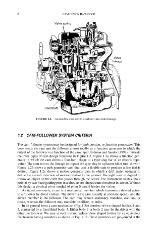
Valve spring
Valve
linkage
Camshaft
FIGURE 1.1. Automobile cam-driven overhead valve train linkage.
1.2 CAM-FOLLOWER SYSTEM CRITERIA
The cam-follower system may be designed for path, motion, or function generation. This
book treats the cam and the follower almost totally as a function generator in which the
output of the follower is a function of the cam input. Erdman and Sandor (1997) illustrate
the three types of cam design functions in Figure 1.2. Figure 1.2a shows a function gen-
erator in which the cam drives a four-bar linkage to a type slug bar of an electric type-
writer. The cam moves the linkage to impact the type slug to a platem roller (not shown).
Figure 1.2b shows a path generator cam that uses a double cam to produce a line that is
desired. Figure 1.2c shows a motion-generator cam in which a drift meter operates to
define the aircraft direction of motion relative to the ground. The sight wire is aligned to
follow an object on the earth that passes through the center. The instrument rotates about
point 0 by two fixed guiding pins in a circular arc-shaped cam slot about its center. Without
this design a physical pivot needed of point 0 would hinder the vision.
As stated previously, a cam is a mechanical member which transmits a desired action
to a follower by direct contact. The driver is the cam (usually at constant speed), and the
driven member is the follower. The cam may remain stationary, translate, oscillate, or
rotate, whereas the follower may translate, oscillate, or index.
In its general form a cam mechanism (Fig. 1.3a) consists of two shaped bodies, 1 and
2, connected by a fixed third body, 3. Either body 1 or body 2 may be the driver with the
other the follower. We may at each instant replace these shaped bodies by an equivalent
mechanism having members as shown in Fig. 1.3b. These members are pin-jointed at the