
Page 17 - Cam Design Handbook
P. 17
THB1 8/15/03 2:42 PM Page 5
INTRODUCTION 5
(a) Radial cam (b) Translating cam
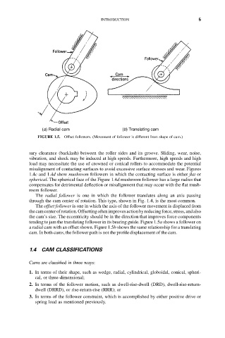
FIGURE 1.5. Offset followers. (Movement of follower is different from shape of cam.)
sary clearance (backlash) between the roller sides and its groove. Sliding, wear, noise,
vibration, and shock may be induced at high speeds. Furthermore, high speeds and high
load may necessitate the use of crowned or conical rollers to accommodate the potential
misalignment of contacting surfaces to avoid excessive surface stresses and wear. Figures
1.4c and 1.4d show mushroom followers in which the contacting surface is either flat or
spherical. The spherical face of the Figure 1.4d mushroom follower has a large radius that
compensates for detrimental deflection or misalignment that may occur with the flat mush-
room follower.
The radial follower is one in which the follower translates along an axis passing
through the cam center of rotation. This type, shown in Fig. 1.4, is the most common.
The offset follower is one in which the axis of the follower movement is displaced from
the cam center of rotation. Offsetting often improves action by reducing force, stress, and also
the cam’s size. The eccentricity should be in the direction that improves force components
tending to jam the translating follower in its bearing guide. Figure 1.5a shows a follower on
a radial cam with an offset shown. Figure 1.5b shows the same relationship for a translating
cam. In both cams, the follower path is not the profile displacement of the cam.
1.4 CAM CLASSIFICATIONS
Cams are classified in three ways:
1. In terms of their shape, such as wedge, radial, cylindrical, globoidal, conical, spheri-
cal, or three-dimensional;
2. In terms of the follower motion, such as dwell-rise-dwell (DRD), dwell-rise-return-
dwell (DRRD), or rise-return-rise (RRR); or
3. In terms of the follower constraint, which is accomplished by either positive drive or
spring load as mentioned previously.