
Page 22 - Cam Design Handbook
P. 22
THB1 8/15/03 2:42 PM Page 10
10 CAM DESIGN HANDBOOK
FIGURE 1.12. Spiral cam. (Pin gear meshes with teeth in cam
groove.)
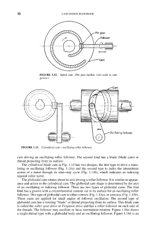
FIGURE 1.13. Cylindrical cam—oscillating roller follower.
cam driving an oscillating roller follower. The second kind has a blade (blade cam) or
thread projecting from its surface.
The cylindrical blade cam in Fig. 1.14 has two designs, the first type to drive a trans-
lating or oscillating follower (Fig. 1.14a) and the second type to index the intermittent
action of a turret through its start–stop cycle (Fig. 1.14b), which indicates an indexing
tapered roller turret.
The globoidal cam rotates about its axis driving a roller follower. It is similar in appear-
ance and action to the cylindrical cam. The globoidal cam shape is determined by the arcs
of an oscillating or indexing follower. There are two types of globoidal cams. The first
kind has a groove with a circumferential contour cut in its surface for an oscillating roller
follower. This type of globoidal cam is either convex (Fig. 1.15a), or concave (Fig. 1.15b).
These cams are applied for small angles of follower oscillation. The second type of
globoidal cam has a twisting “blade” or thread projecting from its surface. This blade cam
is called the roller gear drive or Ferguson drive and has a roller follower on each side of
the threads. The follower may oscillate or have intermittent rotation. Figure 1.16a shows
a single-thread type with a globoidal body and an oscillating follower. Figure 1.16b is an