
Page 21 - Cam Design Handbook
P. 21
THB1 8/15/03 2:42 PM Page 9
INTRODUCTION 9
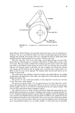
FIGURE 1.11. Conjugate cam—oscillating follower (dual rollers and
cams).
lating follower. Roller followers are generally used in this type of cam for optimum per-
formance. The use of two followers allows one roller to be preloaded against the other to
eliminate the backlash. This design effectively constrains the follower under high speed
and high dynamic loads resulting in lower noise, vibration, and wear.
The wiper cam (Fig. 15.6) is one with a long, curved shape driving a curved or flat-
faced follower with translation or oscillation. The follower is often called a toe by virtue
of its shape. The cam usually oscillates but sometimes may be made to rotate. The wiper
cam slides on the follower surface during its action. If the cam oscillates the cam and the
follower will maintain contact at all times, but with complete cam rotation the surfaces
will separate and the follower will, by spring action or gravity, have a quick return con-
dition so that the cycle can be repeated. The rotating wiper cam has been used as an ore
breaker in stamp mills.
The rolling cam is one with pure rolling between the cam and the follower. It is similar
in appearance and application to the wiper cam, improved by alleviating the detrimental
sliding and surface wear.
The circular-arc cam, as the name implies, is one composed of circular arcs (see Fig.
16.10). This cam is rarely utilized.
The spiral cam, shown in Fig. 1.12, has special grooves in its face that drive a trans-
lating and rotating follower. The pin gear follower is driven by teeth in the cam groove,
and the angular velocity of the follower is determined by the cam radical distance. This
cam has been employed in analog computing systems.
The cylindrical, barrel, or drum cam has a cylindrical shape that rotates about its axis,
and the follower translates or oscillates. Cylindrical cams usually use cylindrical roller fol-
lowers. Sometimes preloaded tapered conical rollers are applied to reduce the slippage and
wear caused by the different driving radii and speeds. In addition, the cylindrical cam has
been employed internally as well as externally. Also, in rare cases, the cylinder may operate
as an “end” cam on its end surface. There are two types of cylindrical cams. The first type
has a circumferential contour cut in its surface. Figure 1.13 shows this kind of cylindrical