
Page 26 - Cam Design Handbook
P. 26
THB1 8/15/03 2:42 PM Page 14
14 CAM DESIGN HANDBOOK
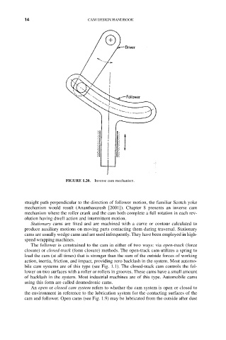
FIGURE 1.20. Inverse cam mechanism.
straight path perpendicular to the direction of follower motion, the familiar Scotch yoke
mechanism would result (Ananthasuresh [2001]). Chapter 8 presents an inverse cam
mechanism where the roller crank and the cam both complete a full rotation in each rev-
olution having dwell action and intermittent motion.
Stationary cams are fixed and are machined with a curve or contour calculated to
produce auxiliary motions on moving parts contacting them during traversal. Stationary
cams are usually wedge cams and are used infrequently. They have been employed in high-
speed wrapping machines.
The follower is constrained to the cam in either of two ways: via open-track (force
closure) or closed-track (form closure) methods. The open-track cam utilizes a spring to
load the cam (at all times) that is stronger than the sum of the outside forces of working
action, inertia, friction, and impact, providing zero backlash in the system. Most automo-
bile cam systems are of this type (see Fig. 1.1). The closed-track cam controls the fol-
lower on two surfaces with a roller or rollers in grooves. These cams have a small amount
of backlash in the system. Most industrial machines are of this type. Automobile cams
using this form are called desmodronic cams.
An open or closed cam system refers to whether the cam system is open or closed to
the environment in reference to the lubrication system for the contacting surfaces of the
cam and follower. Open cams (see Fig. 1.9) may be lubricated from the outside after dust