
Page 29 - Cam Design Handbook
P. 29
THB1 8/15/03 2:42 PM Page 17
INTRODUCTION 17
5
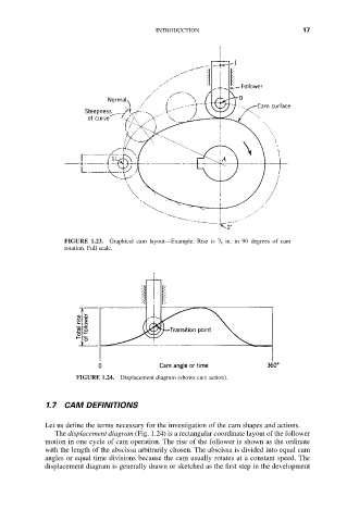
FIGURE 1.23. Graphical cam layout—Example. Rise is / 8 in. in 90 degrees of cam
rotation. Full scale.
FIGURE 1.24. Displacement diagram (shows cam action).
1.7 CAM DEFINITIONS
Let us define the terms necessary for the investigation of the cam shapes and actions.
The displacement diagram (Fig. 1.24) is a rectangular coordinate layout of the follower
motion in one cycle of cam operation. The rise of the follower is shown as the ordinate
with the length of the abscissa arbitrarily chosen. The abscissa is divided into equal cam
angles or equal time divisions because the cam usually rotates at a constant speed. The
displacement diagram is generally drawn or sketched as the first step in the development