
Page 31 - Cam Design Handbook
P. 31
THB1 8/15/03 2:42 PM Page 19
INTRODUCTION 19
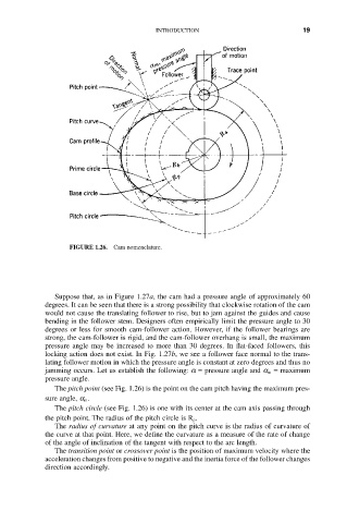
FIGURE 1.26. Cam nomenclature.
Suppose that, as in Figure 1.27a, the cam had a pressure angle of approximately 60
degrees. It can be seen that there is a strong possibility that clockwise rotation of the cam
would not cause the translating follower to rise, but to jam against the guides and cause
bending in the follower stem. Designers often empirically limit the pressure angle to 30
degrees or less for smooth cam-follower action. However, if the follower bearings are
strong, the cam-follower is rigid, and the cam-follower overhang is small, the maximum
pressure angle may be increased to more than 30 degrees. In flat-faced followers, this
locking action does not exist. In Fig. 1.27b, we see a follower face normal to the trans-
lating follower motion in which the pressure angle is constant at zero degrees and thus no
jamming occurs. Let us establish the following: a = pressure angle and a m = maximum
pressure angle.
The pitch point (see Fig. 1.26) is the point on the cam pitch having the maximum pres-
sure angle, a m .
The pitch circle (see Fig. 1.26) is one with its center at the cam axis passing through
the pitch point. The radius of the pitch circle is R p .
The radius of curvature at any point on the pitch curve is the radius of curvature of
the curve at that point. Here, we define the curvature as a measure of the rate of change
of the angle of inclination of the tangent with respect to the arc length.
The transition point or crossover point is the position of maximum velocity where the
acceleration changes from positive to negative and the inertia force of the follower changes
direction accordingly.