
Page 27 - Cam Design Handbook
P. 27
THB1 8/15/03 2:42 PM Page 15
INTRODUCTION 15
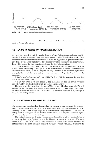
Displacement
(a) Dwell-rise- (b) Dwell-rise-dwell- (c) Dwell-rise- (d) Rise-retrun-
dwell (DRD). return-dwell (DRDRD). return-dwell (DRRD). rise (RRR).
FIGURE 1.21. Types of cams in terms of follower motion.
and contamination are removed. Closed cams are sealed and lubricated by an oil bath,
mist, or forced lubrication.
1.5 CAMS IN TERMS OF FOLLOWER MOTION
As previously stated, one of the special features of cam follower systems is that specific
dwell action may be designed for the follower motion. A dwell is defined as a lack of fol-
lower movement while the cam maintains its input driving action. In production machin-
ery, dwell occurs when the follower does not move while a secondary task is performed.
Figure 1.21 shows the four basic types of cams for the follower action.
Dwell-Rise-Dwell Cam (DRD). This cam type, Figure 1.21a, has a dwell followed by
a rise contour followed by a dwell period at the maximum displacement. It also may have
dwell-fall-dwell action, which is analyzed similarly. DRD cams are utilized in cylindrical
and globoidal cams indexing a rotating turret. In rare cases multiple dwell actions may be
necessary.
A dwell-rise-dwell-return-dwell cam (DRDRD), Fig. 1.21b, incorporates the complete
action cycle of a DRD cam.
A dwell-rise-return-dwell cam (DRRD), Fig. 1.21c, has the rise and return preceded
and followed by dwells. It has limited application in machinery.
The contour of the rise-return-rise cam (RRR), Figure 1.21d, has no dwells. We will
not analyze this type, because an eccentric mechanism (Chap. 15) is usually a better choice
than the cam-follower mechanism. The eccentric mechanism is more accurate, less expen-
sive, and easier to produce.
1.6 CAM PROFILE GRAPHICAL LAYOUT
The manual cam layout method described in this section is used primarily for informa-
tion. In general, designers use CAD digitized packages to generate the cam profile on the
drawing. Cam-follower designs begin with crude sketches using cartesian coordinates, as
in Fig. 1.22. In this figure we see that the cam-follower action may be considered equiv-
alent to a wedge action of infinite length.
The wedge is shown moving at a constant speed from right to left to raise the follower
a maximum distance, h. The first cycle of the follower movement is the curve ABCA¢ con-
tinued to B¢C¢A≤B≤C≤A B , and so forth. A radial cam may be considered a wedge rolled
in the plane of the paper having a length of one cycle (wedge cam ABCA¢) equal to the