
Page 28 - Cam Design Handbook
P. 28
THB1 8/15/03 2:42 PM Page 16
16 CAM DESIGN HANDBOOK
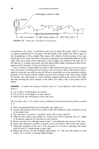
Knife-edge or center of roller
FIGURE 1.22. Wedge cam—equivalent to all cam actions.
circumference of a circle. A cylindrical cam is one in which the wedge ABCA¢ is twisted
in a plane perpendicular to the paper with the length of the wedge cam ABCA¢ equal to
the circumference of the cylinder. The contour AB, which is the rise portion of the cam,
should not be too steep since this will produce jamming of the translating follower on the
sides. This curve slope can be reduced by using a longer cam length for the same rise of
the follower, h. A larger cam results. Also the speed of the wedge is pertinent to later inves-
tigation of the dynamics of the cam-follower action.
Let’s construct a simple radial cam with a roller follower having a given rise in a given
time. The means for finding the cam shape is one of inversion, that is, the profile is devel-
oped by fixing the cam and moving the follower around the cam at its respective relative
positions. If we used an infinite number of points, the envelope of the cam contour would
be formed. Also, the layout of a roller follower requires plotting the center of the roller
and then drawing the curve tangent to the rollers. For clarity, only a few points will be
shown.
1
EXAMPLE A radial cam rotating clockwise drives a / 2 inch diameter roller follower as
follows:
1. rise of 5/8 in. in 90 degrees of rotation
2. fall of 5/8 in. in 90 degrees of cam rotation
3. dwell for the last 180 degrees of the cam cycle
The procedure (Fig. 1.23), which consists of fixing the cam and moving the follower around
it, is:
1. Draw two perpendicular axes locating the cam center at A.
2. Assume the location of the lowest point of the roller-follower center at point 0, on one
of the radial lines.
3. The maximum rise, point 1, should be shown 5/8 in above point 0.
4. With the cam center A and radius A1, swing an arc until it intersects line A1¢, which
is 90 degrees opposite the direction of cam rotation.
5. Draw a smooth curve through points 0 and 1¢, providing the rise portion of the cam.
6. Draw roller diameters and then a tangent curve to the rollers. This is the cam surface.
7. Check the steepness of the curve. If at any point it is excessive, redesign with larger
radii A0 and A1, which means a larger cam.
8. Repeat the process for the 90-degree fall portion 1¢2¢. The last 180 degrees of cam
action 2¢0 is a dwell, a constant radial distance.