
Page 34 - Cam Design Handbook
P. 34
THB1 8/15/03 2:42 PM Page 22
22 CAM DESIGN HANDBOOK
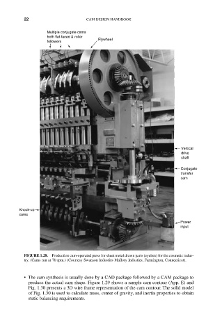
Multiple conjugate cams
both flat-faced & roller
Flywheel
followers
Vertical
drive
shaft
Conjugate
transfer
cam
Knock-up
cams
Power
input
FIGURE 1.28. Production cam-operated press for sheet metal drawn parts (eyelets) for the cosmetic indus-
try. (Cams run at 70 rpm.) (Courtesy Swanson Industies Mallory Industies, Farmington, Connecticut).
• The cam synthesis is usually done by a CAD package followed by a CAM package to
produce the actual cam shape. Figure 1.29 shows a sample cam contour (App. E) and
Fig. 1.30 presents a 3D wire frame representation of the cam contour. The solid model
of Fig. 1.30 is used to calculate mass, center of gravity, and inertia properties to obtain
static balancing requirements.