
Page 36 - Cam Design Handbook
P. 36
THB1 8/15/03 2:42 PM Page 24
24 CAM DESIGN HANDBOOK
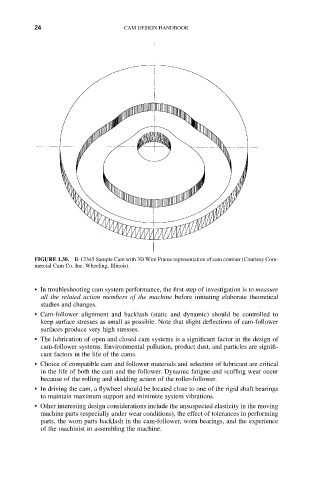
FIGURE 1.30. B-12345 Sample Cam with 3D Wire Frame representation of cam contour (Courtesy Com-
mercial Cam Co. Inc. Wheeling, Illinois).
• In troubleshooting cam system performance, the first step of investigation is to measure
all the related action members of the machine before initiating elaborate theoretical
studies and changes.
• Cam-follower alignment and backlash (static and dynamic) should be controlled to
keep surface stresses as small as possible. Note that slight deflections of cam-follower
surfaces produce very high stresses.
• The lubrication of open and closed cam systems is a significant factor in the design of
cam-follower systems. Environmental pollution, product dust, and particles are signifi-
cant factors in the life of the cams.
• Choice of compatible cam and follower materials and selection of lubricant are critical
in the life of both the cam and the follower. Dynamic fatigue and scuffing wear occur
because of the rolling and skidding action of the roller-follower.
• In driving the cam, a flywheel should be located close to one of the rigid shaft bearings
to maintain maximum support and minimize system vibrations.
• Other interesting design considerations include the unsuspected elasticity in the moving
machine parts (especially under wear conditions), the effect of tolerances in performing
parts, the worn parts backlash in the cam-follower, worn bearings, and the experience
of the machinist in assembling the machine.