
Page 16 - Cam Design Handbook
P. 16
THB1 8/15/03 2:42 PM Page 4
4 CAM DESIGN HANDBOOK
instantaneous centers of curvature, a and b, of the contacting surfaces. At any other instant,
the points a and b are shifted and the links of the equivalent mechanism have different
lengths. Grodinski (1947) and Jones (1967) have excellent compilations of practical cam
mechanisms.
1.3 FOLLOWER TYPES
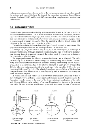
Cam follower systems are classified by referring to the follower or the cam or both. Let
us consider the follower first. The follower movement is translation, oscillation, or index-
ing. The follower surface is knife-edge, flat, curved, or roller. The follower restraint to the
cam is positive-driven by the use of rollers in the cam groove or multiple conjugate cams,
is spring-loaded, or occurs by gravity. Also, the translating follower line of motion with
reference to the cam center may be radial or offset.
The radial translating follower shown in Figure 1.4 will be used as an example. The
popular oscillating follower and the rotating follower are discussed later.
The knife-edge, or point, follower (Fig. 1.4a), is, as the name implies, a sharp edge in
contact with the cam. Although simple in construction, this type of follower is not prac-
tical because it results in excessive wear of the contact point. It is employed in design as
the center of the roller follower.
For proper performance the follower is constrained to the cam at all speeds. The roller
follower, Fig. 1.4b, is the most popular design for accomplishing this criterion. Commer-
cially available roller followers use ball or needle bearings supported by a stem. Positive
drive action is accomplished by a roller follower internally in a cam groove or track (Fig.
1.8), by followers on the opposite side of a single cam (yoke cam, Fig. 1.10), or by con-
jugate dual disk cams (Fig. 1.11). The roller follower has a low coefficient of friction when
compared to the other followers and is most frequently used in production machinery and
some automotive engines.
In contact with the cam surface the follower roller action at low speeds can be that of
pure rolling; however, at higher speeds significant sliding is evident. In groove cams the
fluctuation in roller speeds is the result of the driven rotational acceleration of the roller
as it rides on different radial surfaces of the cam. Experience has shown that the grooved
cam roller follower does not provide exact positive-driven action because of the neces-
Load Load Load Load
(a) Knife-edge (b) Roller (c) Flat-faced (d ) Spherical-faced
follower. follower. follower. follower.
FIGURE 1.4. Types of follower contact surfaces.