
Page 185 - Cam Design Handbook
P. 185
THB6 8/15/03 2:40 PM Page 173
ELEMENTS OF CAM PROFILE GEOMETRY 173
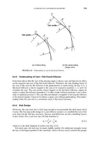
(a) Undercutting. (b) No undercutting
(larger cam).
FIGURE 6.11 Undercutting of cam by flat-faced follower.
6.4.3 Undercutting of Cam—Flat-Faced Follower
It has been shown that the size of the pressure angle is always zero and thus has no effect
on the required cam size of the flat-faced follower. Therefore, the only limiting factor of
the size of the cam for the follower is the phenomenon of undercutting. In Fig. 6.11, a
flat-faced follower is shown tangent to the cam at its respective positions 1, 2, and 3 to
construct the cam. The cam profile, drawn tangent to the flat-faced follower, cannot be
made to contact the follower at position 2. In other words, follower positions 1 and 3 elim-
inate or undercut position 2. The cam thus developed is incapable of driving the follower
in the desired manner. Figure 6.11b shows a larger cam without undercutting. Thus under-
cutting limits the cam size to a minimum value in flat-faced followers.
6.4.4 Hub Design
Obviously, the cam must have a hub large enough to accommodate the shaft upon which
it turns. The first step in the design of a cam-follower system is to establish the size of the
cam shaft and the hub key necessary. Stresses and deflections are the controlling factors
in this choice. For a cast iron cam, the hub diameter is
3 1
d =1 d + in (6.21)
h s
4 4
where d s is the shaft diameter in inches (see Fig. 6.12).
For steel cams, the hub may be made slightly smaller. For additional strength, locate
the key in the largest portion of the cam body, which will also easily establish the proper