
Page 186 - Cam Design Handbook
P. 186
THB6 8/15/03 2:40 PM Page 174
174 CAM DESIGN HANDBOOK
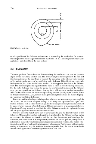
FIGURE 6.12 Hub size.
relative position of the follower and the cam in assembling the mechanism. In practice,
the cam profile is made larger than the hub by at least 1/8 in. This is to prevent stress con-
centrations and short life in the cam surface.
6.5 SUMMARY
The three pertinent factors involved in determining the minimum cam size are pressure
angle, profile curvature, and hub size. The pressure angle is the steepness of the cam and
therefore determines the side thrust or wear of the translating roller follower in its bearing
guide and the performance of an oscillating roller follower. This side thrust exists only
during the rise, i.e., when the follower motion is in the opposite direction to the follower
load. The maximum pressure angle should be made as small as possible during this action.
For the roller follower, this is done by having the coefficient of friction and the follower
stem overhang small and the follower bearing long, with the stem as rigid as possible.
With flat-faced followers, the pressure angle, being constant (usually equal to zero), is not
of design consideration. Also, the side thrust pressure angle effects do not exist with prop-
erly designed oscillating followers.
For most machines having translating roller followers, the maximum pressure angle is
30° or less, but the author has gone as high as 47.5deg with light loads and rigid, low-
friction linkages, such as linear ball bearings. Reduction in pressure angle may be achieved
by using a larger cam, an offset follower, a different cam curve, or a secondary follower.
Equation 6.13 may be used to establish the roller follower cam size for cylindrical cams
and for yielding acceptable accuracy for radial cams.
We have seen that not all cams can be constructed to give the desired motion to the
followers. This condition, called undercutting, is attributed to the follower surface radius
of curvature, the follower acceleration, and the cam size. In concave profiles using roller
followers, the acceleration at q = 0 generally controls. In convex profiles, using either a
roller or flat-faced follower, the maximum negative acceleration controls. The easiest solu-
tion to this problem of undercutting is to employ a larger cam. Furthermore, without under-
cutting, sharp corners may be produced in the cam profile. Last, the hub or shaft size is
another limiting factor in determining the minimum cam size.