
Page 208 - Cam Design Handbook
P. 208
THB7 8/15/03 1:58 PM Page 196
196 CAM DESIGN HANDBOOK
n i
s i
r i
r i
r i+1
O
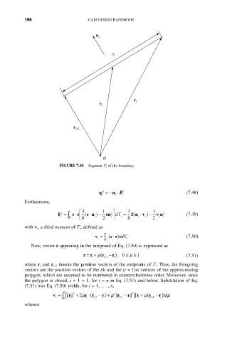
FIGURE 7.10. Segment G i of the boundary.
q =- n J O i (7.48)
O
◊
i
i
Furthermore,
È 3 1 T ˘ 3 1
(
◊
◊
I = r r ( r n ) - rn dG = 1 n v ◊ ) - v n T (7.49)
O
i Ú G Í i i ˙ i i i i i
i Î8 2 ˚ 8 2
with v i, a third moment of G i, defined as
◊ )
v = ( r r rdG (7.50)
i Ú G i
i
Now, vector r appearing in the integrand of Eq. (7.50) is expressed as
£
r =+ ( m r - ), 0 £ m 1 (7.51)
r
r
+ i 1
i
i
where r i and r i+1 denote the position vectors of the endpoints of G i. Thus, the foregoing
vectors are the position vectors of the ith and the (i + 1)st vertices of the approximating
polygon, which are assumed to be numbered in counterclockwise order. Moreover, since
the polygon is closed, i + 1 = 1, for i = n in Eq. (7.51) and below. Substitution of Eq.
(7.51) into Eq. (7.50) yields, for i = 1,..., n,
1
v = [ r 2 + 2m r ◊( r - )+ m 2 r - r ][ r + ( m r - )]
2
r dm
r
i Ú 0 i i i+1 i i+1 i i i+1 i
whence