
Page 324 - Cam Design Handbook
P. 324
THB10 9/19/03 7:28 PM Page 312
312 CAM DESIGN HANDBOOK
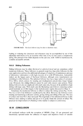
FIGURE 10.23. Flat-faced follower (may be offset to distribute wear).
loading or reducing the clearances and tolerances may be accomplished by use of the
adjustable stud shown or by an eccentric roller stud, or by (in rare cases) a compression
spring. The preload of the rollers depends on the cam size, with -0.001in interference fit,
a usually acceptable amount.
10.9.3 Sliding Followers
Sliding followers may be either flat-faced or spherical faced and are sometimes called
mushroom followers. These followers in general weigh less than roller followers for the
same application and have the additional advantages of simplicity of maintenance and ease
of lubrication. Lubrication is with high-viscosity oil or with EP lubrication. Automobile
makers are the largest users of flat-faced followers, although some manufacturers are
switching to roller followers. The spherical follower face has a large radius of curvature,
30 to 300in, which corrects for wearing and misalignment and provides longer fatigue
wear. Obviously this sliding follower cannot be used with concave cam surfaces. These
sliding followers also are employed with small cams only, because of the prohibitive high
sliding with large cams. With small cams the fluctuating cam-follower contacting surface
speed maintains an oil film largely in the hydrodynamic regime discussed in Chap. 8.
Sometimes the mushroom follower is offset to reduce the sliding action (Fig. 10.23).
The rise or fall of the follower is unaffected by the offset. However, the follower is now
rotating and translating (corkscrew action), giving sliding and rolling of the cam. The area
of contact and wear life is thus increased. The magnitude of the unbalanced forces on the
follower stem, tending to deflect and jam it in its guide, limits the amount of offset. The
practical net improvement of offsetting in this manner is subject to controversy.
10.10 CONCLUSION
All machined surfaces (with the exception of MEMS, Chap. 15) are generated and
functionally operated under the influence of impact and impulsive forces of variable