
Page 320 - Cam Design Handbook
P. 320
THB10 9/19/03 7:28 PM Page 308
308 CAM DESIGN HANDBOOK
Load
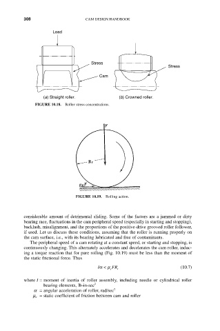
Stress
Stress
Cam
(a) Straight roller. (b) Crowned roller.
FIGURE 10.18. Roller stress concentrations.
FIGURE 10.19. Rolling action.
considerable amount of detrimental sliding. Some of the factors are a jammed or dirty
bearing race, fluctuations in the cam peripheral speed (especially in starting and stopping),
backlash, misalignment, and the proportions of the positive-drive grooved roller follower,
if used. Let us discuss these conditions, assuming that the roller is running properly on
the cam surface, i.e., with its bearing lubricated and free of contaminants.
The peripheral speed of a cam rotating at a constant speed, or starting and stopping, is
continuously changing. This alternately accelerates and decelerates the cam roller, induc-
ing a torque reaction that for pure rolling (Fig. 10.19) must be less than the moment of
the static frictional force. Thus
Ia < m s FR r (10.7)
where I = moment of inertia of roller assembly, including needle or cylindrical roller
bearing elements, lb-in-sec 2
a = angular acceleration of roller, rad/sec 2
m s = static coefficient of friction between cam and roller