
Page 317 - Cam Design Handbook
P. 317
THB10 9/19/03 7:28 PM Page 305
CAM MANUFACTURING 305
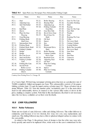
TABLE 10.1 Spare Parts List, Newspaper Press Subassembly Folding Couple
Key Name Key Name Key Name
FC-1. Stud FC-21. Roller Bearing FC-41. Gear for Pin Cam
FC-2. Adjusting Lug FC-22. Bearing Plate FC-42. Eccentric Bushing
FC-3. 2nd Fold Roller FC-23. Adjusting Lug FC-43. Shaft
Gear FC-24. Folding Cylinder FC-44. Bearing
FC-4. End Plate Gear Rim FC-45. Gear for Pin Cam
FC-5. Sleeve FC-25. Gear Rim Hub FC-46. Gear Hub
FC-6. Plate On Gear FC-26. Bevel Drive Gear FC-47. Washer
Housing FC-27. Bevel Gear On FC-48. Stud
FC-7. Gear Housing Shaft FC-49. Rotating Pin Cam
FC-8. Folding Blade FC-28. Oil Seal FC-50. Collar
Shaft Gear FC-29. Spacer FC-51. Pin Lever Shaft
FC-9. Intermediate Gear FC-30. Key FC-52. Cutting Cylinder
FC-10. Folding Blade FC-31. Washer FC-53. Cutting Rubber
FC-11. Folding Blade Shaft FC-32. Horizontal Drive FC-54. Knife Bar Assembly
FC-12. Folding Cylinder Shaft FC-55. Pin Lever Shaft
FC-13. Bridge FC-33. Roller Bearing FC-56. Gear Rim
FC-14. Bridge FC-34. Cutting Cylinder FC-57. Shim
FC-15. Pin Cam Lever Drive Gear FC-58. End Plate
FC-16. Stud and Roller FC-35. Backlash Gear FC-59. Capscrew
FC-17. Folding Cylinder FC-36. Adjusting Stud FC-60. Gear Hub
Yoke FC-37. Oil Seal
FC-18. Folding Pin Cam FC-38. Plate for Cutting
FC-19. Second Fold Cylinder
Roller Levers FC-39. Spacer
FC-20. Folding Cylinder FC-40. Plate for Cutting
Sleeve Cylinder
Courtesy Goss Printing Press Co. Chicago, Ill.
of a 3-story high, 90-foot-long newspaper printing press that runs at a production rate of
70,000 completely folded newspapers per hour. This subassembly consists of the paper-
folding cylinder (part 12) and the paper-cutting cylinder (part 52). These cylinders run at
about 500rpm. Table 10.1 lists the number parts. Incidentally, part 32 is the main drive
shaft for the subassembly shown. It connects to the various other series of drives in the
press, making a complex system. Note that in this mechanism a flywheel is not necessary
since the two heavy cylinders act as their own flywheels.
10.9 CAM FOLLOWERS
10.9.1 Roller Followers
There are two kinds of cam followers: roller and sliding followers. The roller follower is
commonly used because of its low friction, low wear, low cost, easy replacement, and
small size. The sliding follower may have a flat or spherical-shaped surface in contact with
the cam profile.
As stated in the Chap. 9, the primary basis of design is that the roller may wear rela-
tively quickly and need to be replaced often, while wear on the cam is minimized. In this