
Page 315 - Cam Design Handbook
P. 315
THB10 9/19/03 7:28 PM Page 303
CAM MANUFACTURING 303
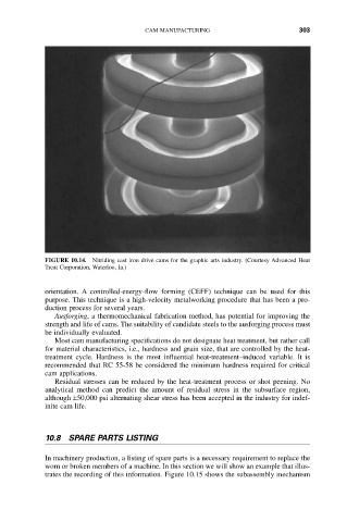
FIGURE 10.14. Nitriding cast iron drive cams for the graphic arts industry. (Courtesy Advanced Heat
Treat Corporation, Waterloo, Ia.)
orientation. A controlled-energy-flow forming (CEFF) technique can be used for this
purpose. This technique is a high-velocity metalworking procedure that has been a pro-
duction process for several years.
Ausforging, a thermomechanical fabrication method, has potential for improving the
strength and life of cams. The suitability of candidate steels to the ausforging process must
be individually evaluated.
Most cam manufacturing specifications do not designate heat treatment, but rather call
for material characteristics, i.e., hardness and grain size, that are controlled by the heat-
treatment cycle. Hardness is the most influential heat-treatment–induced variable. It is
recommended that RC 55-58 be considered the minimum hardness required for critical
cam applications.
Residual stresses can be reduced by the heat-treatment process or shot peening. No
analytical method can predict the amount of residual stress in the subsurface region,
although ±50,000 psi alternating shear stress has been accepted in the industry for indef-
inite cam life.
10.8 SPARE PARTS LISTING
In machinery production, a listing of spare parts is a necessary requirement to replace the
worn or broken members of a machine. In this section we will show an example that illus-
trates the recording of this information. Figure 10.15 shows the subassembly mechanism