
Page 357 - Cam Design Handbook
P. 357
THB11 9/19/03 7:34 PM Page 345
CAM SYSTEM MODELING 345
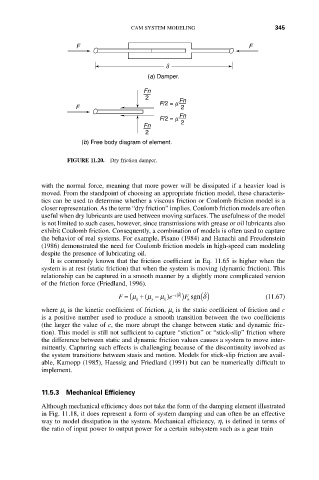
F F
d
(a) Damper.
Fn
2 Fn
F/2 = m
F 2
Fn
F/2 = m
Fn 2
2
(b) Free body diagram of element.
FIGURE 11.20. Dry friction damper.
with the normal force, meaning that more power will be dissipated if a heavier load is
moved. From the standpoint of choosing an appropriate friction model, these characteris-
tics can be used to determine whether a viscous friction or Coulomb friction model is a
closer representation. As the term “dry friction” implies. Coulomb friction models are often
useful when dry lubricants are used between moving surfaces. The usefulness of the model
is not limited to such cases, however, since transmissions with grease or oil lubricants also
exhibit Coulomb friction. Consequently, a combination of models is often used to capture
the behavior of real systems. For example, Pisano (1984) and Hanachi and Freudenstein
(1986) demonstrated the need for Coulomb friction models in high-speed cam modeling
despite the presence of lubricating oil.
It is commonly known that the friction coefficient in Eq. 11.65 is higher when the
system is at rest (static friction) that when the system is moving (dynamic friction). This
relationship can be captured in a smooth manner by a slightly more complicated version
of the friction force (Friedland, 1996).
F = (m + (m - m e ) - c d ˙ F ) sgn () d ˙ (11.67)
k s k n
where m k is the kinetic coefficient of friction, m s is the static coefficient of friction and c
is a positive number used to produce a smooth transition between the two coefficients
(the larger the value of c, the more abrupt the change between static and dynamic fric-
tion). This model is still not sufficient to capture “stiction” or “stick-slip” friction where
the difference between static and dynamic friction values causes a system to move inter-
mittently. Capturing such effects is challenging because of the discontinuity involved as
the system transitions between stasis and motion. Models for stick-slip friction are avail-
able, Karnopp (1985), Haessig and Friedland (1991) but can be numerically difficult to
implement.
11.5.3 Mechanical Efficiency
Although mechanical efficiency does not take the form of the damping element illustrated
in Fig. 11.18, it does represent a form of system damping and can often be an effective
way to model dissipation in the system. Mechanical efficiency, h, is defined in terms of
the ratio of input power to output power for a certain subsystem such as a gear train