
Page 355 - Cam Design Handbook
P. 355
THB11 9/19/03 7:33 PM Page 343
CAM SYSTEM MODELING 343
shock absorbers) or the system fits a form easily modeled as with the examples in Chen
(1982), damping values are usually obtained experimentally.
Damping results from motion, and as such, experimental determination of damping is
complicated by the fact that the system must be maintained in motion in order to gener-
ate damping forces. As a result, it is rarely worth the effort to fixture each component
separately to estimate its damping. Furthermore, since frictional effects occur at the
interface between components, it may even be impossible to determine the amount of
damping by looking at components individually. Because of these issues, damping is
usually determined experimentally by choosing a form or forms of damping and using
experimental data from the overall system to fit the parameters in those forms. Thus
damping is often added to a system model after masses and stiffnesses have been deter-
mined and the appropriate reductions made. Accordingly, the approach of this section is
somewhat different than the previous sections. Instead of the main focus being on the com-
bination of individual damping elements, this section focuses on describing the broad
classes of damping models commonly encountered and appropriate conditions for the use
of each.
11.5.1 Viscous or Speed-Dependent Damping
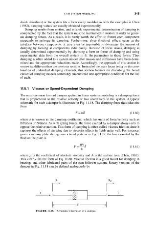
The most common form of damper applied in linear systems modeling is a damping force
that is proportional to the relative velocity of two coordinates in the system. A typical
schematic for such a damper is illustrated in Fig. 11.18. The damping force thus takes the
form
F = bd ˙ (11.60)
where b is known as the damping coefficient, which has units of force/velocity such as
lbf/(in/s) or N/(m/s). As with spring forces, the force exerted by a damper always acts to
oppose the relative motion. This form of damping is often called viscous friction since it
captures the effects of damping due to viscosity effects in fluids quite well. For instance,
given a moving plate sliding over a fixed plate as in Fig. 11.19, the force exerted by the
fluid on the plate is
m A
F = d ˙ (11.61)
h
where m is the coefficient of absolute viscosity and A is the surface area (Chen, 1982).
This clearly fits the form of Eq. 11.60. Viscous friction is a good model for damping in
bearings and other lubricated parts of the cam-follower system. Rotary versions of the
damper in Fig. 11.18 can be defined analogously by
X 1 X 2
F F
d
FIGURE 11.18. Schematic illustration of a damper.