
Page 350 - Cam Design Handbook
P. 350
THB11 9/19/03 7:33 PM Page 338
338 CAM DESIGN HANDBOOK
d
F F
A
L
FIGURE 11.13. Rod in axial compression.
K 1
F K 2 F
d
L f
(a) Springs in parallel.
K eq
F F
d
L f
(b) Equivalent single spring.
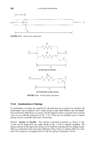
FIGURE 11.14. Parallel spring equivalence.
11.4.3 Combinations of Springs
If combinations of springs are connected by elements that are assumed to be massless, the
combination can be replaced with a single spring of equivalent stiffness and free length.
The need for this often arises as a result of model reduction where a mass has been assumed
to be zero (as with the suspension in Fig. 11.3c). There are two possible ways to connect
springs, known as parallel and series connections.
11.4.3.1 Springs in Parallel. Two springs connected in parallel, as shown in Fig.
11.14a, can be replaced by the single spring in Fig. 11.14b to simplify modeling. The
spring constant for the equivalent spring can be found by realizing that two springs in par-
allel are constrained to have the same deflection. Thus, if the two springs deflect by a dis-
tance d in response to an applied force F, the first spring will produce a force