
Page 347 - Cam Design Handbook
P. 347
THB11 9/19/03 7:33 PM Page 335
CAM SYSTEM MODELING 335
d
l
D
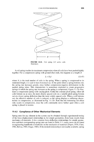
FIGURE 11.11. Coil spring (2.5 active coils
illustrated).
A coil spring reaches its maximum compression when all coils have been pushed tightly
together. For a compression spring with ground (flat) ends, this happens at a length of
L = N d (11.47)
t
where N t is the total number of coils in the spring. When a spring is compressed to its
minimum length, it is said to have bottomed out. At the point where a spring bottoms out,
the spring rate increases greatly, since further compression requires deformation in the
packed spring wires. This characteristic is sometimes exploited to create progressive
springs in which the spring rate increases as the spring is compressed. Figure 11.12a illus-
trates a compression spring with varying pitch. Unlike the constant pitch spring, where all
coils bottom out at once, the more closely spaced coils on a variable pitch spring bottom
out at a lower spring deflection than the more widely spaced coils. When a coil bottoms
out, the effective number of coils is reduced, so the spring displays a stiffening charac-
teristic in compression, as illustrated in Fig. 11.12b. Note that the bottoming out effect
only occurs in compression, since the coils continually move further apart when a coil
spring is placed in tension.
11.4.2 Compliance of Other Mechanical Elements
Spring rates for any element in the system can be obtained through experimental testing
of the force-displacement relationship or, for simple geometries, from basic results from
mechanics of materials. A few common force-deflection relationships for simple geome-
tries and their corresponding spring rates are listed in Table 11.1; many more can be found
in engineering handbooks or textbooks on the mechanics of materials (Popov, 1976, Chen,
1982, Relvas, 1985, Ungar, 1985). If the desired relationship is not readily available, spring