Page 351 - Cam Design Handbook
P. 351

THB11  9/19/03  7:33 PM  Page 339

                                    CAM SYSTEM MODELING                    339

                                          F =  K d                       (11.48)
                                           1   1
            while the second spring produces a force
                                          F =  K d.                      (11.49)
                                           2   2
            The sum of these forces must equal the applied force F so
                                  F =  F +  F = ( K +  K ) =  K d.       (11.50)
                                                  d
                                                      eq
                                                 2
                                         2
                                             1
                                      1
            Clearly, the equivalent spring stiffness is therefore
                                        K =  K +  K .                    (11.51)
                                         eq   1  2
            Since the equivalent stiffness is simply the sum of the two individual spring stiffnesses,
            if the two springs have very different stiffnesses, the equivalent stiffness will be domi-
            nated by the spring with higher stiffness.
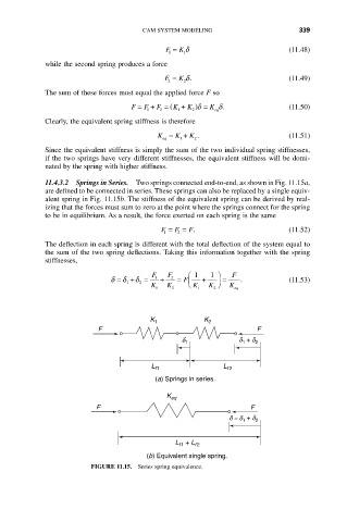
            11.4.3.2 Springs in Series.  Two springs connected end-to-end, as shown in Fig. 11.15a,
            are defined to be connected in series. These springs can also be replaced by a single equiv-
            alent spring in Fig. 11.15b. The stiffness of the equivalent spring can be derived by real-
            izing that the forces must sum to zero at the point where the springs connect for the spring
            to be in equilibrium. As a result, the force exerted on each spring is the same
                                         F =  F =  F.                    (11.52)
                                          1  2
            The deflection in each spring is different with the total deflection of the system equal to
            the sum of the two spring deflections. Taking this information together with the spring
            stiffnesses,
                                       F   F    Ê 1  1  ˆ  F
                             d = d + d =  1  +  2  = Á  +  ˜ =  .        (11.53)
                                               F
                                1   2
                                       K  K     Ë K  K  ¯  K
                                        1   2     1   2    eq
                                      K 1           K 2
                         F                                       F
                                              d 1           d + d
                                                             1
                                                                2
                                       L f 1            L f 2
                                        (a) Springs in series.

                                          K eq
                         F                                     F
                                                          d = d + d
                                                             1   2

                                             L  + L f 2
                                             f 1
                                     (b) Equivalent single spring.
                        FIGURE 11.15.  Series spring equivalence.
   346   347   348   349   350   351   352   353   354   355   356