
Page 348 - Cam Design Handbook
P. 348
THB11 9/19/03 7:33 PM Page 336
336 CAM DESIGN HANDBOOK
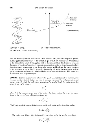
F
Last coil
bottoms
First pair of
coils bottom
Next coil
bottoms
d (tension) d (compression)
(a) Shape of spring. (b) Force-deflection curve.
FIGURE 11.12. Variable-pitch coil spring.
rates can be easily derived from a basic stress analysis. First, choose a simplified geome-
try that approximates the shape of the element in question. Next, calculate the stress arising
in the element as a result of the applied load. If it is assumed that the element is acting in
the region of elastic deformation (a reasonable assumption for the systems in question here
since they must be designed to survive cyclic motion and loading), the stress can then
easily be related to strain. Finally, the deflection can be calculated from the strain and the
spring rate determined from this relationship between force and deflection. This procedure
is illustrated by a simple example.
EXAMPLE Suppose a system uses a long rod (Fig. 11.13) loaded axially to transmit force
between members (this is in fact the case in pushrod engines). The rod does not in fact
remain perfectly rigid, but deflects as a result of the applied load. The axial stress that
arises in the rod is given by
F
s =
A
where A is the cross-sectional area of the rod. In the linear region, the strain is propor-
tional to the stress through Young’s modulus, so
s F
e = = .
E EA
Finally, the strain is simply deflection per unit length, so the deflection of the rod is
FL
d = L e = .
EA
The spring rate follows directly from this expression, so for the axially loaded rod
F EA
K = = .
d L