Page 363 - Cam Design Handbook
P. 363

THB11  9/19/03  7:34 PM  Page 351

                                    CAM SYSTEM MODELING                    351

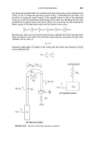
            arm, the pushrod and the lifter now assumed rigid, the system takes on the schematic form
            of Fig. 11.24a. To obtain the equivalent system of Fig. 11.24b reflected to the lifter, it is
            necessary  to  equate  the  kinetic  energy  of  the  original  system  to  that  of  the  equivalent
            system to account for the mechanical advantage of the rocker arm. Recalling that the mass
            contribution of a spring fixed at one end is a third of its mass at the free end, equating the
            kinetic energy of the equivalent system and the original system gives
                       1      1      1       1      1       1 1
                        mv =    m v +  m v +  J w  2  +  m v +  m v .
                                                                  2
                                                         2
                                   2
                            2
                                          2
                       2  eq l  2  f l  2  pr pr  2  ra  ra  2  vsvs  2 3  csvs
            Kinematically, there are several relationships between velocities that follow from the mod-
            eling assumptions made earlier. Since the lifter and pushrod are assumed to be rigid, their
            velocities are the same, so
                                          v = .
                                              v
                                           pr  l
            Assuming small angles of rotation on the rocker arm, the rocker arm rotational velocity
            can be obtained from
                                            v    v
                                      w =    l  =  vs  .
                                        ra
                                           l ra pr  l ra vs
                                             ,
                                                  ,
                           l ra,pr  l ra,vs

                             J ra
                                                                       K eq


                               w  ra
                                             X vs, V vs

                                                      x , v l       m eq
                                                      l
               X pr, V pr    m pr
                                      m vs
                                              m cs
                                               3        (b) Equivalent system.
                                           K cs


               x , v l   m l
                l


                         (a) Rigid body system.
               FIGURE 11.24.  Valve-gear system after rigid body assumptions.
   358   359   360   361   362   363   364   365   366   367   368