
Page 365 - Cam Design Handbook
P. 365
THB11 9/19/03 7:34 PM Page 353
CAM SYSTEM MODELING 353
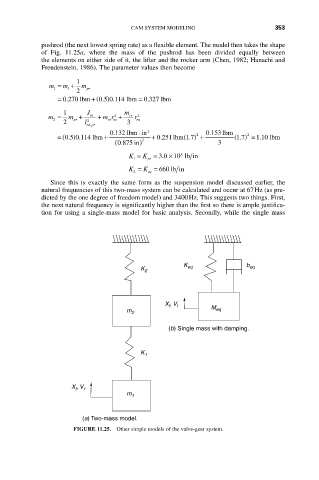
pushrod (the next lowest spring rate) as a flexible element. The model then takes the shape
of Fig. 11.25a, where the mass of the pushrod has been divided equally between
the elements on either side of it, the lifter and the rocker arm (Chen, 1982; Hanachi and
Freudenstein, 1986). The parameter values then become
1
m = m + m pr
1
l
2
0327 lbm
= . + ( . ) . = .
0270 lbm
05 0114 lbm
1 J m
2
m = m + ra + mr + cs r ra 2
vs ra
pr
2
2
2 l ra pr 3
,
◊
0132 lbm in 2 0153 lbm
.
.
2
0251 lbm
.
05 0114 lbm
= ( . ) . + + . (1.7 ) + ( 17) =. 2 110 lbm
(0.875 in ) 2 3
K = K = 3010 lb in
5
¥
.
1 pr
K = K = 660 lb in
2 eq
Since this is exactly the same form as the suspension model discussed earlier, the
natural frequencies of this two-mass system can be calculated and occur at 67Hz (as pre-
dicted by the one degree of freedom model) and 3400Hz. This suggests two things. First,
the next natural frequency is significantly higher than the first so there is ample justifica-
tion for using a single-mass model for basic analysis. Secondly, while the single mass
K b
K 2 eq eq
X , V l
l
m 2 M eq
(b) Single mass with damping.
K 1
X , V r
l
m 1
(a) Two-mass model.
FIGURE 11.25. Other simple models of the valve-gear system.