
Page 373 - Cam Design Handbook
P. 373
THB12 9/19/03 7:34 PM Page 361
CAM SYSTEM DYNAMICS—ANALYSIS 361
Damping value ranges from 4 to 8 percent in most cam-and-follower systems; it is the
transient response of the follower that is of basic concern. Steady-state vibration
in most systems rarely occurs, because in practice the angular velocity of the camshaft
is low in comparison with the natural frequency of the follower system. We assume
that the vibration damps out during the dwell period and does not carry over to the next
motion cycle.
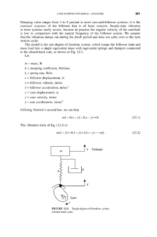
The model is the one-degree-of-freedom system, which lumps the follower train and
mass load into a single equivalent mass with equivalent springs and dampers connected
to the closed-track cam, as shown in Fig. 12.1.
Let
m = mass, lb
b = damping coefficient, lb/in/sec
k = spring rate, lb/in
x = follower displacement, in
.
x = follower velocity, in/sec
x ¨ = follower acceleration, in/sec 2
y = cam displacement, in
.
y = cam velocity, in/sec
y ¨ = cam acceleration, in/sec 2
Utilizing Newton’s second law, we see that
mx b x ˙ - )+ ( y) = 0 . (12.1)
˙˙ + (
k x -
y ˙
The vibration form of Eq. (12.1) is
mx ˙˙ ˙˙)+ ( y ˙ k x - y) =- my ˙˙. (12.2)
b x ˙ - )+ (
(
y
-
x Follower
m
b
k
y
Cam
FIGURE 12.1. Single-degree-of-freedom system
(closed-track cam).