
Page 377 - Cam Design Handbook
P. 377
THB12 9/19/03 7:34 PM Page 365
CAM SYSTEM DYNAMICS—ANALYSIS 365
n = 2
cam
n = 3
n = 5
Acceleration Amplification T t
n = 0.5
n = 1
w
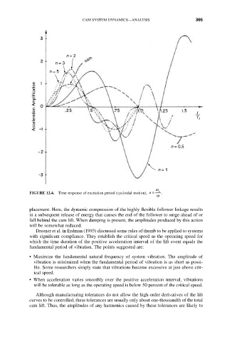
FIGURE 12.4. Time response of excitation period (cycloidal motion), n = n .
w
placement. Here, the dynamic compression of the highly flexible follower linkage results
in a subsequent release of energy that causes the end of the follower to surge ahead of or
fall behind the cam lift. When damping is present, the amplitudes produced by this action
will be somewhat reduced.
Dresner et al. in Erdman (1993) discussed some rules of thumb to be applied to systems
with significant compliance. They establish the critical speed as the operating speed for
which the time duration of the positive acceleration interval of the lift event equals the
fundamental period of vibration. The points suggested are:
• Maximize the fundamental natural frequency of system vibration. The amplitude of
vibration is minimized when the fundamental period of vibration is as short as possi-
ble. Some researchers simply state that vibrations become excessive at just above crit-
ical speed.
• When acceleration varies smoothly over the positive acceleration interval, vibrations
will be tolerable as long as the operating speed is below 50 percent of the critical speed.
Although manufacturing tolerances do not allow the high-order derivatives of the lift
curves to be controlled, these tolerances are usually only about one-thousandth of the total
cam lift. Thus, the amplitudes of any harmonics caused by these tolerances are likely to