
Page 379 - Cam Design Handbook
P. 379
THB12 9/19/03 7:34 PM Page 367
CAM SYSTEM DYNAMICS—ANALYSIS 367
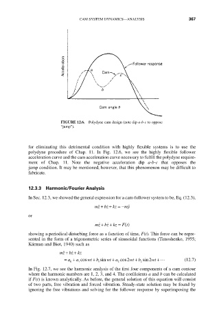
FIGURE 12.6. Polydyne cam design (note dip a-b-c to oppose
“jump”).
for eliminating this detrimental condition with highly flexible systems is to use the
polydyne procedure of Chap. 11. In Fig. 12.6, we see the highly flexible follower
acceleration curve and the cam acceleration curve necessary to fulfill the polydyne require-
ment of Chap. 11. Note the negative acceleration dip a-b-c that opposes the
jump condition. It may be mentioned, however, that this phenomenon may be difficult to
fabricate.
12.3.3 Harmonic/Fourier Analysis
In Sec. 12.3, we showed the general expression for a cam-follower system to be, Eq. (12.3),
˙ +
˙˙+
mz bz kz = - my ˙˙
or
˙˙
mz bz kz = ()
+
˙
+
F t
showing a periodical disturbing force as a function of time, F(t). This force can be repre-
sented in the form of a trigonometric series of sinusoidal functions (Timoshenko, 1955;
Kárman and Biot, 1940) such as
+
˙˙
+
˙
mz bz kz
+
+
= a + a cos wt b sin wt a cos2 wt b sin2 wt + L (12.7)
+
0 1 1 2 2
In Fig. 12.7, we see the harmonic analysis of the first four components of a cam contour
where the harmonic numbers are 1, 2, 3, and 4. The coefficients a and b can be calculated
if F(t) is known analytically. As before, the general solution of this equation will consist
of two parts, free vibration and forced vibration. Steady-state solution may be found by
ignoring the free vibrations and solving for the follower response by superimposing the