
Page 382 - Cam Design Handbook
P. 382
THB12 9/19/03 7:34 PM Page 370
370 CAM DESIGN HANDBOOK
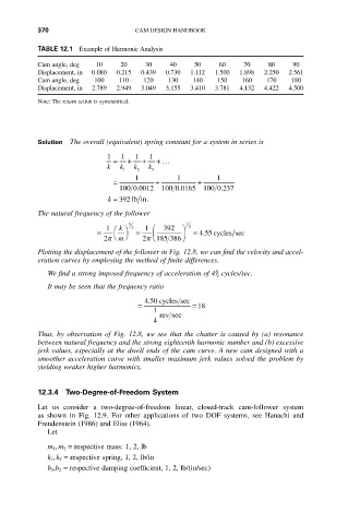
TABLE 12.1 Example of Harmonic Analysis
Cam angle, deg 102030405060708090
Displacement, in 0.080 0.215 0.439 0.730 1.112 1.500 1.898 2.250 2.561
Cam angle, deg 100 110 120130140150160170180
Displacement, in 2.789 2.949 3.049 3.155 3.410 3.781 4.132 4.422 4.500
Note: The return action is symmetrical.
Solution The overall (equivalent) spring constant for a system in series is
1 1 1 1
= + + + ...
k k k k
1 2 3
1 1 1
= + +
.
.
.
100 0 0012 100 0 0165 100 0 237
k = 392 lb in .
The natural frequency of the follower
1 1
1 Ê k ˆ 2 1 Ê 392 ˆ 2
= = Á ˜ = 455 cycles sec
.
Ë
2p m ¯ 2p Ë185 386 ¯
Plotting the displacement of the follower in Fig. 12.8, we can find the velocity and accel-
eration curves by employing the method of finite differences.
1
We find a strong imposed frequency of acceleration of 4/ 2 cycles/sec.
It may be seen that the frequency ratio
.
450 cycles sec
= =18
1
rev sec
4
Thus, by observation of Fig. 12.8, we see that the chatter is caused by (a) resonance
between natural frequency and the strong eighteenth harmonic number and (b) excessive
jerk values, especially at the dwell ends of the cam curve. A new cam designed with a
smoother acceleration curve with smaller maximum jerk values solved the problem by
yielding weaker higher harmonics.
12.3.4 Two-Degree-of-Freedom System
Let us consider a two-degree-of-freedom linear, closed-track cam-follower system
as shown in Fig. 12.9. For other applications of two DOF systems, see Hanachi and
Freudenstein (1986) and Eliss (1964).
Let
m 1 , m 2 = respective mass: 1, 2, lb
k 1 , k 2 = respective spring, 1, 2, lb/in
b 1 ,b 2 = respective damping coefficient, 1, 2, lb/(in/sec)