
Page 387 - Cam Design Handbook
P. 387
THB12 9/19/03 7:34 PM Page 375
CAM SYSTEM DYNAMICS—ANALYSIS 375
the energy stored in the shaft is released and drives the cam at an increasing speed, thus
causing the follower mass to catch up with the forcing cam action and then to overshoot
it. In this section (Szakallas and Savage, 1980), we will present the dynamic investigation
of two basic types of models:
• The “open-track” cam-follower system uses a spring-loaded follower to constrain the
follower to the cam. The spring force is transmitted to the cam at all times in which the
torque on the cam drive has the same frequency as the rotation of the cam.
• The “closed-track” cam-follower system uses rollers constrained in cam grooves or, as
in the conjugate design, dual rollers on two cams. It is seen that the closed-track system
subjected to an inertia load will have significant compliances to yield twice the fre-
quency of the cam speed. This phenomenon affects both the torsion and flexure in the
shaft.
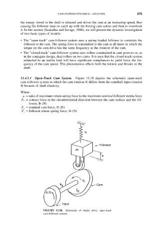
12.4.2.1 Open-Track Cam System. Figure 12.10 depicts the schematic open-track
cam-follower system in which the cam rotation q c differs from the camshaft input rotation
q i because of shaft elasticity.
Where
a = ratio of maximum return spring force to the maximum nominal follower inertia force
F h = contact force in the circumferential direction between the cam surface and the fol-
lower, lb (N)
F n = nominal cam force, lb (N)
F s = follower return spring force, lb (N)
k f
Follower
q c
Cam
q (t)
i
Input
FIGURE 12.10. Schematic of elastic drive, open-track
cam-follower system.