
Page 392 - Cam Design Handbook
P. 392
THB12 9/19/03 7:34 PM Page 380
380 CAM DESIGN HANDBOOK
.05
b m
Q = 50
m
25
.04
10
5
.03
1
.1
.02
.01
0
0 5 10 15 20
h
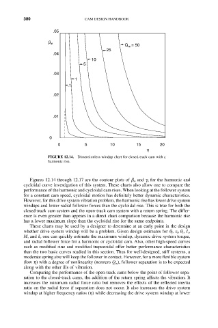
FIGURE 12.14. Dimensionless windup chart for closed-track cam with a
harmonic rise.
Figures 12.14 through 12.17 are the contour plots of b m and g n for the harmonic and
cycloidal curve investigation of this system. These charts also allow one to compare the
performance of the harmonic and cycloidal cam rises. When looking at the follower system
for a constant cam speed, cycloidal motion has definitely better dynamic characteristics.
However, for this drive system vibration problem, the harmonic rise has lower drive system
windups and lower radial follower forces than the cycloidal rise. This is true for both the
closed-track cam system and the open-track cam system with a return spring. The differ-
ence is even greater than appears in a direct chart comparison because the harmonic rise
has a lower maximum slope than the cycloidal rise for the same endpoints.
These charts may be used by a designer to determine at an early point in the design
whether drive system windup will be a problem. Given design estimates for q f, x f, q s, I c,
M, and k s one can quickly estimate the maximum windup, dynamic drive system torque,
and radial follower force for a harmonic or cycloidal cam. Also, other high-speed curves
such as modified sine and modified trapezoidal offer better performance characteristics
than the two basic curves studied in this section. Thus for well-designed, stiff systems, a
moderate spring size will keep the follower in contact. However, for a more flexible system
(low h) with a degree of nonlinearity (nonzero Q m), follower separation is to be expected
along with the other ills of vibration.
Comparing the performance of the open-track cams below the point of follower sepa-
ration to the closed-track cams, the addition of the return spring affects the vibration. It
increases the minimum radial force ratio but removes the effects of the reflected inertia
ratio on the radial force if separation does not occur. It also increases the drive system
windup at higher frequency ratios (h) while decreasing the drive system windup at lower