
Page 397 - Cam Design Handbook
P. 397
THB12 9/19/03 7:34 PM Page 385
CAM SYSTEM DYNAMICS—ANALYSIS 385
x
m 2
F v
x F v
m 2
y
m 1
k f F h
m 1
y
f
R
Cam
··
q c q c
I c
I c
T
k s
Input
q i
(a) Schematic. T
T k s
q c
q i Input
(b) Free body diagrams.
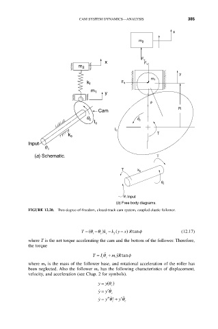
FIGURE 12.20. Two-degree-of-freedom, closed-track cam system, coupled elastic follower.
T = (q i -q c k ) - k y x Rtan f (12.17)
(
- )
f
s
where T is the net torque accelerating the cam and the bottom of the follower. Therefore,
the torque
˙˙
I
T = q ˙˙ + m yRtanf
cc
1
where m 1 is the mass of the follower base, and rotational acceleration of the roller has
been neglected. Also the follower m 1 has the following characteristics of displacement,
velocity, and acceleration (see Chap. 2 for symbols).
y = q
y()
c
˙
y = y¢q ˙ c
˙
y = y¢¢q ˙ 2 + y¢q ˙˙
c c