
Page 398 - Cam Design Handbook
P. 398
THB12 9/19/03 7:34 PM Page 386
386 CAM DESIGN HANDBOOK
which yields
y¢ )
T = q ˙˙ + m Rtanf y¢¢ ( q ˙ 2 + q ˙˙ (12.18)
I
cc 1 c c
y = Rtanfq ˙ = y¢q ˙
c c
y¢ = Rtan . (12.19)
f
Therefore, from Eqs. (12.17), (12.18), and (12.19)
( q - ) + k x y y ) ¢ - m y y ¢¢ q ¢ 2 ˙ = ( I + m y¢ 2 ˙˙
(
-
q k
q ) .
i c s f 1 c c 1 c
Summing forces on mass m 2 at the follower top
(
mx ˙˙ = k y x .- ) (12.20)
f
2
If there is no model mass m 1 those terms in the equation will be eliminated.
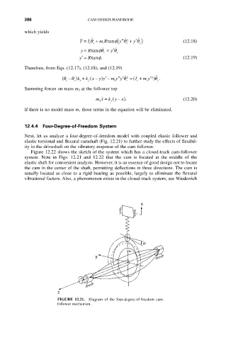
12.4.4 Four-Degree-of-Freedom System
Next, let us analyze a four-degree-of-freedom model with coupled elastic follower and
elastic torsional and flexural camshaft (Fig. 12.21) to further study the effects of flexibil-
ity in the driveshaft on the vibratory response of the cam follower.
Figure 12.22 shows the sketch of the system which has a closed-track cam-follower
system. Note in Figs. 12.21 and 12.22 that the cam is located at the middle of the
elastic shaft for convenient analysis. However, it is an essence of good design not to locate
the cam in the center of the shaft, permitting deflections in three directions. The cam is
usually located as close to a rigid bearing as possible, largely to eliminate the flexural
vibrational factors. Also, a phenomenon exists in the closed-track system, see Wiederrich
x
a
y
z
FIGURE 12.21. Diagram of the four-degree-of-freedom cam-
follower mechanism.